A DIY microscope build for examining rock samples
In the summer of 2017 I went on a trip to Halifax with my girlfriend Anne. She studied geology at Dalhousie and gave me a tour of her old department and labs. The best part was the petrology lab, where geos examine extremely thin (~30um) slices of rocks under special microscopes to figure out what minerals they contain. At these thicknesses the rocks are translucent, so you can illuminate them from below and look at the light that passes through.
While the microscopes looked like normal bright-fields from afar, they were different from the ones that I used in my Master’s studies in a couple important ways. First, the sample stage was set up to rotate about the optical axis instead of translating in x and y. Second, there were a number of linearly polarizing filters in the microscope that you could slide into and out of place. The effect of these filters was downright bizarre. Check it out in the video clip below - a polarizing filter gets flicked into the optical path a second or two into the clip.
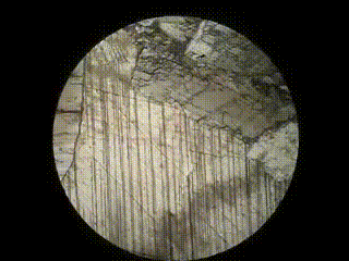
Calcite crystals seen within a rock sample, with and without the cross-polarizing analyzer
A few observations:
- Holy crap, that’s awesome!
- Only certain crystals seem to be producing the rainbow effect
- The crystals that go rainbow seem to be turned on and off as the slide rotates, whereas the crystals that stay normal maintain their brightness throughout the rotation
- The on and off positions for each individual crystal are exactly 90 degrees apart from each other.
- The on and off positions for separate crystals don’t seem to be related to each other
In this post we try to figure out the physics that drives this effect. In the next one I’ll go over how to make a simple microscope out of wood and some cheap optical components to observe it for yourself.
Polarization
To understand this effect we first have to understand polarized light. Light is a transverse electromagnetic wave, so if the light is traveling along the z-direction then the electric field that drives it is oscillating in the x-y plane. As with all waves, the principle of superposition holds – you can break a wave down in to two components, do whatever analysis you need to, then add the resulting parts back up together at the end and your result will match what happens in the physical world.
It’s convenient of represent the polarization of a particular light source with a vector, whose length is the magnitude of the wave and whose direction represents the direction of vibration. So light can be polarized in the x-direction, in the y-direction, and it can be polarized at an angle, which, thanks to superposition, we can treat as the sum of a bit of x-polarized light and a bit of y-polarized.
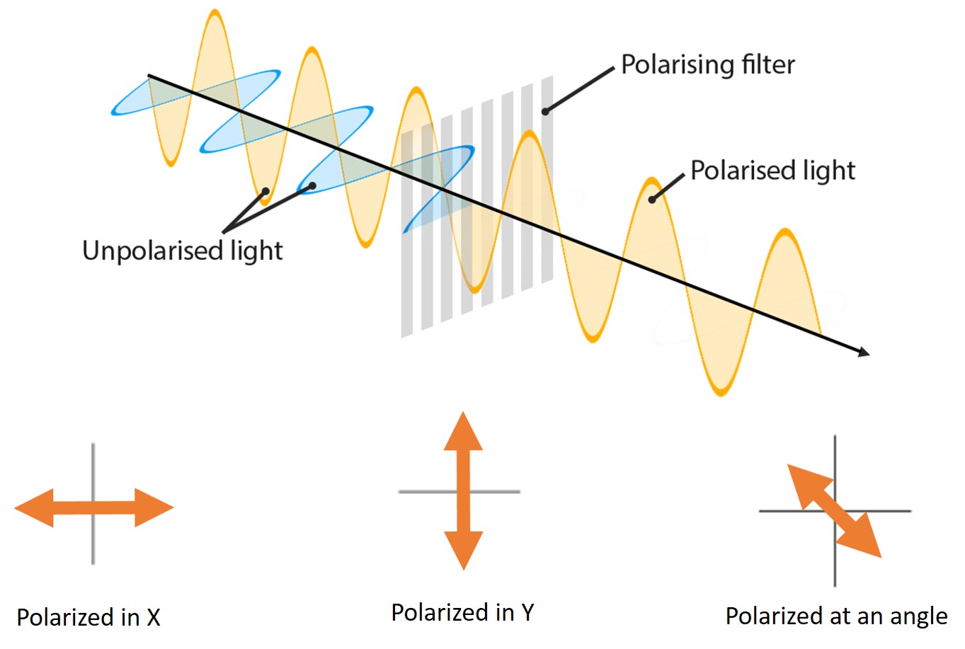
Light passing through a polarizing filter has all of its components extinguished except for the component parallel to the direction of the filter
If you start with an unpolarized source and pass it through a linearly polarized filter, only the components of the source that are polarized in the same direction as the filter pass through. If a second filter is put in place perpendicular to the first one, it too will only admit the light that is polarized in its direction, which in this case is exactly zero. Any vector dot x dot y = 0, since x and y are normal. If you and a friend have polarized sunglasses you can see it for yourself; hold one pair normally and the other pair sideways in front of it – blackout.
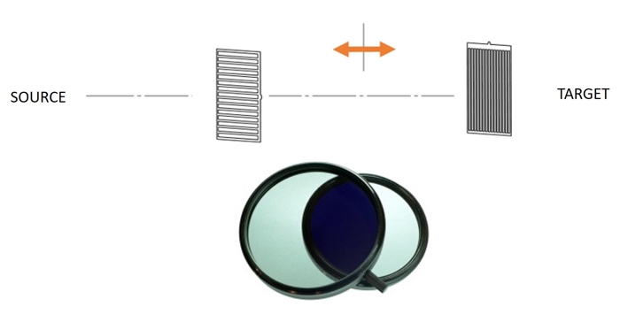
Two linearly polarized filters held together at 90 degrees causes all the light to become extinguished. After passing through the first filter the light is purely left-to-right polarized, none of which can pass through the second
OK, so far so good. Now it gets funky. To understand what was happening with the rocks earlier, we need to understand an optical property of some materials called birefringence, meaning the material has two different refractive indices for light vibrating in the x and y directions. The chunk of calcite on the left image splits the light coming from the grid paper in two, and refracts the x light and the y light different amounts, resulting in a doubled grid showing through. This difference stems from the fact that these materials are crystals, and that their structure is anisotropic.
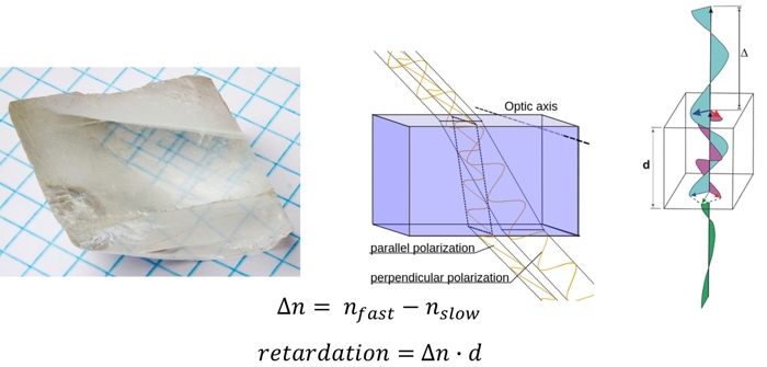
Birefringence. Left: a chunk of calcite showing image twinning due to its high birefringent index. Center: A diagram of what's going on within the calcite. Right: The path and phase difference that happens to the two components of light when it passes through a birefringent material of thickness d
Call one direction the fast direction (light travels further in one wave cycle if vibrating in this direction) and the other the slow direction (light travels less far in one wavelength).
If we shine some polarized light on a birefringent material, and that light is polarized somewhere in between the fast and slow directions, then we can put superposition to work again and split the light into a fast and slow component. The fast component makes it through the material first, separated from the slow component by a distance called the retardation, which is equal to the difference in refractive indices times the thickness of the material.
If the retardation is equal to an integer multiple of the wavelength, the fast and slow components recombine perfectly in phase and we the microscopist don’t notice anything strange. If not, the effect of the crystal is to produce a phase lag between the fast and slow waves.
OK, so birefringent materials can split up polarized light and induce a phase lag between the fast and the slow components. So what. Well, mathematically a phase lag can be treated exactly like a change in polarization.
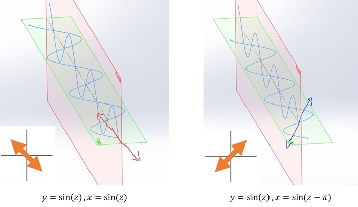
Shifting the phase of one component of a wave produces a change in the direction of polarization. In this case a 1/2 wavelength shift gives a 90 degree rotation in polarization
Look at the two waves in the figure above. They’re shown as the sum of two waves, one in the green plane and one in the red. When viewed from the front, the left wave would appear to be polarized in the up-left to down-right direction: the green wave is at its leftmost point when the red wave is at its highest. If we take the horizontal component of that left wave and drag it back by half a phase, we get the wave on the right. Look at what happened to the polarization by doing that! The red plane wave is now at its highest when the green-plane wave is at its rightmost. It’s now polarized in the up-right to down-left direction.
A half-wavelength phase lag produced a 90 degree rotation in polarization. This is the key to understanding this optical effect. Polarized light passing through a birefringent material of the right thickness will have its polarization direction rotated by 90 degrees.
Okay, back to the microscope. A standard petrology microscope has a linearly polarized filter, then the place for the sample, then another linearly polarized filter at 90 degrees to the first one. As we went over before, two polarized filter at 90 degrees to each other will extinguish any incident light. Unless something funky happens to the light in between the two!
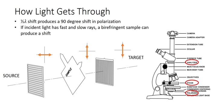
Left: Tracking the polarization of light as it passes through the filter, the sample, then the analyzer of a petrology microscope. The 90 degree rotation of polarity thanks to the birefringence of the sample allows some light to make it through. Right: Components of a petrology microscope
To recap what we’ve seen so far:
- Birefringent materials split light into a slow component and a fast component based on the orientation of the axis of the material’s crystal structure
- When the fast and slow components recombine their relative phase is shifted, based on how powerfully retarding the material was
- A relative phase shift is mathematically equivalent to a change in direction of polarization
- The only way to get light through two perpendicular polarizing filters is to do something to modify the polarization of the light when it’s in-between the filters
- A birefringent material can perform just that modification
Whew! OK, so we’re partway to understanding this phenomenon. But if we look back at the video clip there’s vivid color involved, where does that come from?
Recall that we want our crystal to produce an exactly 90 degree rotation in polarization in order to get light from the y-polarized filter through the x-polarized one. And to get that 90 degree rotation the crystal needs to provide a 1/2 wavelength retardation. Well, what’s half a wavelength for light? It depends on the color.
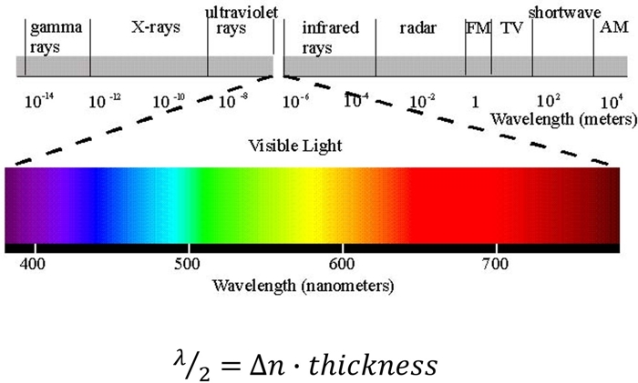
The visible portion of the electromagnetic spectrum spans from wavelengths of ~400-700nm. Given a fixed material thickness and birefringent index, you can solve for what color of light will produce a 1/2 wavelength shift.
OK, the last question was about why the colorful chunks in the video seemed to turn on and off every 90 degrees. The simplest way to understand this is through a hand-wavy thought experiment.
These neat birefringent effects all occur because the crystal splits incident light into a fast wave (aligned with one crystal axis) and a slow wave (perpendicular to that axis). What if the light incident on the crystal was already aligned with the crystal axis? That is, what if the light hitting the crystal were already 100% ‘fast?’ In that case there is no slow wave to shift, no resulting polarization rotation, and no light gets through the second filter in the microscope. The name for this phenomenon is ’extinguishing.’ The same thing occurs if the incident light were 100% ‘slow;’ there is no relative phase shift because the fast wave just doesn’t exist. If you crunch the numbers you find that the greatest intensity of light makes it through to the viewer when the incident light is aligned at 45 degrees to the crystal axis (for equal parts slow and fast light).
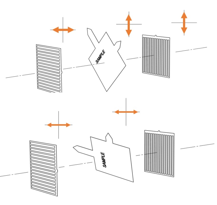
An illustration of extinguishing behavior as we rotate the sample. The fast and slow axes of the crystal are represented by the long and short arrows in the sample block, respectively
In the figure above, the top example shows light hitting the crystal polarized at 45 degrees to its fast axis, which means it has a fast ray and slow ray of equal magnitude. The retarding effect of the crystal causes the relative phase lag which causes the rotation in polarization, bringing it into alignment with the second filter. In the bottom example, we’ve rotated the sample 45 degrees so the light hitting the sample is perfectly aligned with its fast axis - there is no slow axis component. No retardation, no phase shift, no change in polarity, so the light that hits the second filter remains polarized in the left-to-right direction so none gets through. Extinguished.
If we start with the sample loaded so that it’s fast axis is at 0 degrees, we’ll have bright spots at 45, 135, 225, and 315 degrees, and dark patches at 0, 90, 180 and 270. Of course within a rock sample not all of the individual crystals will be aligned with each other, so they don’t all turn on and off at the same time. But each one will switch at 45 degree intervals, for a total of 4 on-off cycles per revolution.
Long post! In the next article I’ll go over the construction of a microscope that lets you observe this effect.