These Boots is another silly robotics project based off of someone else’s legwork. In its finished form it should be a pair of robots that you can stand in, which propel themselves (and you along with em!) using a number of linkage mechanisms designed to simulate walking.
A walking gait produced by a planar linkage and a motor
Linkages are good fun and can produce some really interesting motion patterns from relatively simple underlying geometry. An interesting, if impractical, application of linkages in mobile robotics is for a walking drive mechanism. Instead of wheels or treads like almost every other robot, a linkage can be used to give a motion path to the robots ‘foot’ that slides it backward along the ground, lifts it up, then brings it forward through the air to return to the starting position. If you felt like justifying such a drive mechanism you might say it allows you to step over obstacles that might impede treads or wheels, but you’d be missing the point which is walking robots look hilarious.
Swiggity swooty
The clip above comes from the extraordinarily talented Amanda Ghassaei. She did some research into walking linkages based on the work of artist and engineer Theo Jansen. In particular she was interested in a linkage that possessed the following properties:
- Is driven by a rotating shaft i.e. motor
- Maintains as flat a stroke as possible during the on-the-ground segment of its cycle
- Maintains as even a speed as possible during the on-the-ground segment of its cycle
- Has a brief return segment relative to its on-the-ground segment
- Has high clearance during the return segment of its cycle
She produced an easy-to-read thesis detailing the design of such a linkage and how she arrived at it. What she ended up with looks like two four-bar linkages coupled together:
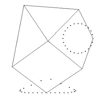
The geometric design of the Ghassaei linkage and a point cloud showing the location of its foot at evenly spaced points in its cycle. Image taken from Amanda Ghassaei’s undergraduate thesis report
She even built a giant scale walking machine out of PVC pipe that uses several of these linkages as feet, but it couldn’t support its own weight. I’d like to build a scaled down version (two in fact!), about the size of a shoebox, out of conventional engineering materials and outfit it with a power and comms system to allow it to move on its own. The ultimate goal is to build something strong enough to stand on, allowing me to outsource the tough work of walking to two poor robots. For this reason I’m calling the project “These Boots,” and hopefully they will be made for walking.
The first order of business was a proof of concept – I wanted to make a quick and dirty version to learn a little more about a few things:
- How many legs would be required per side to provide a not-too-tippy ride
- How to couple the legs together (i.e. how to set the relative phase in their cycle)
- What overall scale would be suitable
- How to best make the joints, providing enough clearance for the links to pass over them through their stroke
- How the joints and links might buckle and sag under load
I drew up a simple assembly in Solidworks matching Amanda’s link lengths and tacked on some gears. A nice thing about linkages is that they tend to be planar, lending themselves to really easy manufacturing if you have access to a laser-cutter or a waterjet. Site 3 has a laser that I used for the job.
With parts in hand I had to figure out how to put them together. This meant creating a box to act as the backboard for legs on both sides, and pinning the linkages together at the joints. I’ve always struggled with the details in simple revolute joints like this, simply because there’s such a range in solutions. At one end you have the high-power machine designers telling you you need pairs of preloaded ball bearings installed in precision housings, RAWR! On the other you have hobbyists that recommend just riveting the two pieces together and putting a piece of paper in between the links to act as a shim when you tighten the rivet. It can’t be that bad of a technique, scissors seem to work great right? I still don’t know the secret to cheap, smooth, not-too-sloppy pinned joints.
What I ended up going for was the super quick and super dirty solution of just shoving wooden dowels everywhere. I had some soft 3/16” dowel stock at home, so I drilled out all the linkage holes to that nominal size, cut up chunks of dowel as needed and shoved em in. Grotesque, but hey it worked!
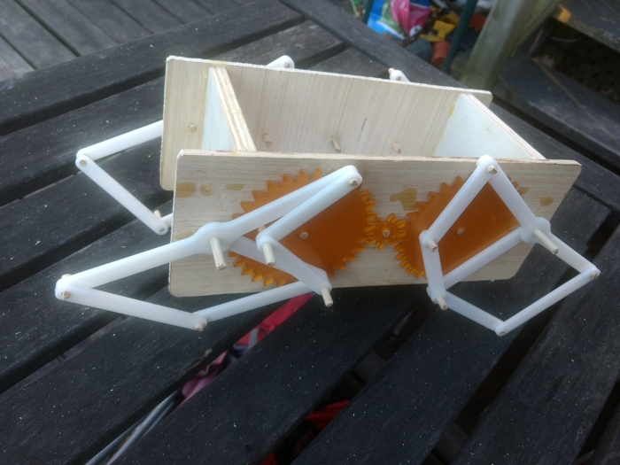
Standing, but just barely
Just for fun I glued a dowel to the main drive gear, chucked it in a cordless drill and let fly. The linkage worked as I hoped; any friction from the dowel pin joints was easily overcome and it didn’t wobble itself apart too easily.
One major pain point for now and for the future were clearances. This linkage design involves a lot of parts that pass over top of each other, so making sure that the links stay in-plane and that the joints don’t extend out too far one way or another is critical. Easy enough to do on a prototype run, but it’ll require real thought
Based on this model I’m going to say I need at least 6 linkage feet per robot to provide a smooth ride. With just 4 there are inevitable certain parts of the stroke in which multiple feet are off the ground (the linkage spends x% of its stroke lifted, meaning that a 4 legged robot has an average of 1.x legs off the ground over its cycle). This would make for an exceptionally tippy ride. With 3 legs per side you could set their phases so that the middle leg on one side would be engaged when the front and back on the opposite are, and vice-versa, always leaving you with a nice centered triangle of support.
One thing to be seen is if the linear speed of the foot in the on-the-ground stroke is consistent enough in velocity that we don’t get multiple feet trying to drag the robot along at different speeds. I’m not sure exactly what the consequences of that would be but sliding isn’t really in the gameplan.
Based on this I have a few jobs ahead of me in order to scale this up to something I can stand on:
- Figure out the linkage material and thickness required to support ~300lbs / 2 robots / 6 legs = ~25 lbs of load
- Devise a solution for the pinned joints that doesn’t involve poplar dowels
- Figure out how to work around whatever clearance issues that solution presents
- Calculate an appropriate gear ratio, source a motor and gearbox to get me there
- Build build build!