In 4th year at Queen’s I built a control system for a double inverted pendulum alongside some of my EngPhys classmates. This is a canonical controls problem, largely because the system is highly unstable and cannot be solved with a PID controller. Since there are three state variables (two joint angles and the position of the base) and only one control input (the force delivered to the base from the motor), you need a more sophisticated controls approach. We used a state-space controller with a full observer and managed to get the apparatus up and balancing in the wee hours of the morning before it was due.
A late night project demo. Please excuse the giddiness, we were quite excited to get it workingThis project taught me a lot about how to do instrumentation right, because quite frankly we did a lot of things wrong. Instead of optical encoders to measure joint angles we used potentiometers. Instead of a microcontroller to assemble the data and relay it back to the computer running the control loop we used a ghastly NI DAQ, essentially a breakout bord for a RS-232 port. Instead of using a motor controller we fed our control signal into a gigantic amplifier and hooked the motor up to that. And yet the project worked. Kinda.
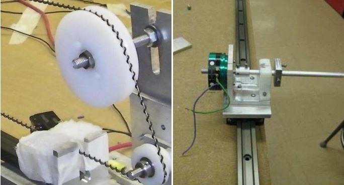
Mechanical details of the build. Left: A nifty helical timing belt coupled the motor to the cart. Right: The base of the pendulum was a cart that slid along a 1m rail. We later regretted using a sliding contact, as modeling friction was an unnecessary headache.
Unfortunately the documentation on this project in terms of photos and video was subpar, so all I have to offer is the above video and our final report.